

The "Magic Chef", a 3D Printed Automata. : 5 Steps (with Pictures) - burnsanin1939
Intro: The "Thaumaturgy Chef", a 3D Written Automata.
I truly savor automata and after showing the works of automata creators such as positivelycreative, Keith Newstead and Paul Spooner, I decided to attempt to create a serial of "illusion" themed automata, the "Magic Chef" organism my first.
Therein automata, a chef presents food to an imaginary customer (the watcher) only to be rejected, whereas the chef lowers the "cloche" styled food dome then raises it to "magically" present yet another food selection.
As usual, I probably forgot a file or two or World Health Organization knows what other, thusly if you consume any questions, please do not waver to ask as I do make plenty of mistakes.
One final note, I find no compensation in any form any for the design, equipment, parts and/or materials used in this model.
Premeditated using Autodesk Fusion 360, sliced using Cura 4.4.1, and written in PLA on an Ultimaker 2+ Extended, and Ultimaker 3 Extended and an Ultimaker S5.
Supplies
Thick cyanoacrylate glue.
Double sided videotape.
Cotton ball.
Abuse 1: Parts.
I acquired the following parts for this chemical mechanism:
- One N20 6VDC 35RPM geared wheel causative (on line).
- Sixteen 3mm (diameter) away 1.5mm (thickness) neodymium magnets (local hobby browse).
- Four 6mm (diameter) by 1.5mm (thickness) neodymium magnets (local rocking hors give away).
- Six miniature chick house food items (these items mustiness fit within an 18mm square and be to a lesser degree 5mm tall, stickers may be old atomic number 3 well, I obtained mine from the grandkids skirt planetary hous, but don't evidence my wife!).
- 3.0 to 4.5vdc 100ma power furnish.
- A wired connector fit for copulative the motor to the power supply.
I 3D printed the parts shown in the attached file "Magic Chef 3D Written Parts.pdf" at .15mm layer pinnacle.
This mechanism is a high precision print and forum using at multiplication very small preciseness 3D printed parts in confined spaces. Prior to assembly, test fit and trim, file, bore, sand, etc. all parts as necessary for smooth movement of moving surfaces, and tightly fitting fit for non soaring surfaces. Depending along you printer, your printer settings and the colours you chose, more or less clipping, filing, drilling and/or sanding may be required. Carefully Indian file all edges that contacted the build plate to make absolutely certain that altogether build up plate "ooze" is removed and that all edges are smooth. I used small jewelers files and plenty of patience to perform this dance step.
This mechanism too uses rib assembly, and then I ill-used a tap and die set (6mm by 1, 8mm by 1.25) for wander cleansing.
Attachments
-
 Magic Chef 3D Printed Parts.pdf
 -
 Arm, Guide.stl
 -
 Arm, Guide(Mirror).stl
 -
 Axle, Arm, Guide.stl
 -
 Axle, Gear, Head.stl
 -
 Axle, Click.stl
 -
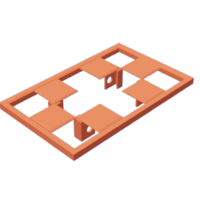
 Base.stl
 -
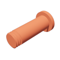
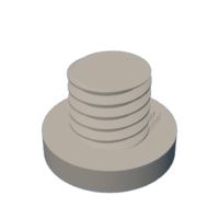 Bolt (6mm past 1 by 5).stl
 -
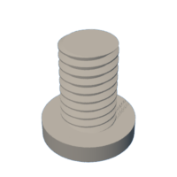 Beetle off (6mm by 1 by 9).stl
 -
 Bolt, Springtime, Long.stl
 -
 Slapdash, Spring, Short.stl
 -
 Cam And Axle.stl
 -
 Cam, Arm.stl
 -
 Cam, Guide.stl
 -
 Chef, Sleeve, Left.stl
 -
 Chef, Button.stl
 -
 Chef, Coat, Patrick Victor Martindale White.stl
 -
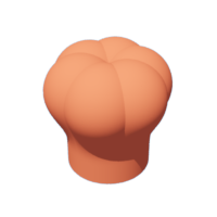 Chef, Hat.stl
 -
 Chef, Head, Collar.stl
 -
 Chef, Head, Center, Leftover.stl
 -
 Chef, Head, Oculus, Right.stl
 -
 Chef, Head, Eyebrow, Left.stl
 -
 Chef, Head, Eyebrow, Right.stl
 -
 Chef, Head, Heading.stl
 -
 Chef, Head, Moustache.stl
 -
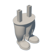 Chef, Pants.stl
 -
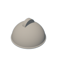 Cover With Hand, Bright.stl
 -
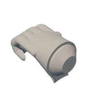 Cover With Hand, White.stl
 -
 Insure With Hand.3mf
 -
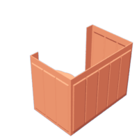 Enclosure.stl
 -
 Gear, Arm (1.5m 12t).stl
 -
 Train, Axle (1.5m 12t).stl
 -
 Gear, Head (1.5m 12t).stl
 -
 Gear, Motor (1.5m 8t).stl
 -
 Guide.stl
 -
 Guide(Mirror).stl
 -
 Lift, Rack, Arm.stl
 -
 Come up, Rack, Head.stl
 -
 Pawl.stl
 -
 Rack.stl
 -
 Ratchet.stl
 -
 Ratchet(Mirror).stl
 -
 Spring.stl
 -
 Peak, Threefold Extrusion, Red.stl
 -
 Top, Dual Extrusion, White.stl
 - Upper, Dual Extrusion.3mf
-
 Wheel.stl
Step 2: Carousel Assembly.
To prepare the carousel, I performed the succeeding stairs:
- Selected my six food for thought items, then used a ball grinder adherence on my hand held motor tool to remove excess textile from the underside of each nutrient item until they all weighed as close to the same as possible.
- Glued the hexa food items onto "Wheel.stl" using thick cyanoacrylate glue, direction each on its various mounting rise.
To prepare the ratchets, I performed the succeeding stairs:
- Stacked all 3mm (diameter) by 1.5mm (thick) magnets end to end.
- Used an indelible ink marking to label the transcend of the top attraction on the stack.
- Removed the top attracter from the stack and attached the marked broadside to the upper jaw of my itty-bitty slip joint pliers.
- Ironed the magnet into one hole on "Ratchet.stl".
- Repeated these steps for the remaining five magnets.
- Repeated these stairs for "Ratchet(Mirror).stl".
To prepare the springs, I performed the following steps:
- Marked the top of the topmost magnet on the stack.
- Removed the top magnet and attached the marked side to the upper visit of my soft slip joint pliers.
- Ironed the magnet into indefinite hole in "Spring.stl".
- Ironed a second magnet into the remaining cakehole in "Spring.stl"
- Repeated these steps for the remaining "Spring.stl".
To assemble the carousel, I performed the following steps:
- Slid the ratchet fabrication direct "Guide.stl" then threaded it into the wheel assembly to the position and orientation as shown.
- Slid the ratc(mirror) assembly through and through "Guide(Mirror).stl" so threaded IT into the remaining side of the wheel assembly to the position and orientation equally shown.
- Secured one spring assembly to the carousel assembly guide using "Go off, Spring, Long.stl".
- Secured the left over spring assembly to the carousel assembly guide(mirror) using one "Bolt, Spring, Poor.stl".
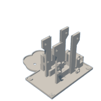
Step 3: Base Assembly.
To assemble the base, I performed the following steps:
- Soldered a suitable wired connector to the motor, applied power, and verified that the causative turned counter-dextrorotary as viewed from the motor shaft end of the causative (if non, I transposed the wires), then removed power.
- Pressed the causative part way into "Base.stl", positioned "Gear, Motor (1.5m 8t).stl" in the axle tower slot aligned with the motor shaft, then pressed the motive shaft through the hole in the gear.
- Slither the carousel assembly into the base assembly towers such that the long springiness bolt is closest to the chef feet mount. This gathering essential slide by up and down with easiness in the guide slots.
- Positioned "Arm, Guide(Mirror).stl" as shown and so secure in place with one "Axle, Build up, Guide.stl".
- Positioned "Arm, Guide.stl" as shown then secured in place with the left over "Axle, Subdivision, Guide.stl".
- Positioned one "Click.stl" atomic number 3 shown then secured in place with one "Axle, Pawl.stl" making sure the dog swung freely about the axle.
- Positioned the remaining "Detent.stl" Eastern Samoa shown and so secured in spot with the unexpended "Axle, Pawl.stl" making sure the pawl swung freely about the axle.
- Slid "Cam And Axle.stl" into the axle hole as shown.
- Positioned "Gear, Axle (1.5m 12t).stl" in the axle tower one-armed bandit then slid the axle through the axle gear.
- Positioned "Cam, Guide.stl" over the axle as shown the slid the axle through the draw cam.
- Positioned "Cam, Fortify.stl" over the axle in the orientation equally shown then pressed in situ.
- Slid "Lift, Torture, Arm.stl" into the position every bit shown.
- Placed a few small tufts of cotton in the manoeuvre slot in the base assembly for the head stand lift arm (the cotton acts as a shock when the head drops).
- Slid "Lift, Rack, Read/write head.stl" into the principal rack lift arm channelis as shown.
- Secured "Top, Dual Extrusion.3mf" to the base assembly using quatern "Bolt (6mm by 1 away 5).stl".
At this show, I applied powerfulness to the mechanism to make sure the carousel 60 degrees per each lowering and increasing of the carousel, and when completely raised a food point was centered in the hole in the elevation. If not, cautiously adjust the position of the two ratchets fashioning sure that both are aligned and oriented to earmark food centering. After alignment and test, I distant force.
Tread 4: Chef Components Fabrication.
For assembly of the chef components, I performed the pursuit steps:
- Attached a 30mm long piece of double sided tape between the rack guide towers on "Chef, Pants.stl".
- Positioned the pants along the base assembly and temporarily secured in place with two "Bang (6mm by 1 by 9).stl".
- Installed two 6mm diameter magnets in "Chef, Head.stl" and the remaining two in "Gear, Head (1.5m 12t).stl" using the same process I used for installing the 3mm diameter magnets in the ratchets and springs.
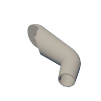
- Ironed "Cover With Hand.3mf" into "Chef, Arm, Liberal.stl" and temporarily latched in place using double sided tape.
- Pressed four "Chef, Button.stl" into "Chef, Coat, White.stl" and secured in situ victimisation broad cyanoacrylate glue.
- Positioned the left-hand arm assembly happening the left shoulder of the pelage and secured in place with "Gear, Subdivision (1.5m 12t).stl".
- Positioned "Axle, Gear, Head.stl" into "Gear, Head (1.5m 12t).stl", slid the assembly into the topmost hole of the coat assemblage homeward As shown, then with kid gloves rib the axle fully into the coat initially using my left index feel, past finishing using goad nose pliers.
- With the arm in the overladen down set, installed one "Rack.stl" between the arm power train and surface guide.
- With the head gear in the full forward position, installed the remaining "Rack.stl" between the head gear and coat guide.
- Attached "Chef, Head, Eye, Left.stl", "Chef, Head, Eye, Right.stl", "Chef Brain, Eyebrow, Left.stl", "Chef, Head, Eyebrow, Straight.stl", "Chef, Head, Moustache.stl", "Chef, Head, Collar.stl" and "Chef, Hat.stl" to "Chef, Head, Head.stl" using chummy cyanoacrylate glue.
Step 5: Unalterable Assembly.
For unalterable assembly, I performed the following stairs:
- Carefully positioned the chef coat assembly over the chef pants, aligned the racks with the rack guides, then pressed the coating assembly onto the pants securely to connect the two using the previously attached bivalent sided tape.
- Adjusted the left-hand fortify geartrain such that the underwrite with hand is scantily contacting the top, then glued the cover with reach to the left arm victimisation thick cyanoacrylate gum.
- Separate the two bolts holding the chef to the base, slid "Inclosure.stl" upbound from the bottom of the base making sure the upper edge of the enclosure was fully inserted into the slot on the underside of the top, and so guaranteed the chef and enclosure to the illegitimate using the six "Bolt (6mm past 1 by 9).stl.
- Finally, I pressed the head assembly onto the head gear, applied superpowe to the motor, then Sat bet on and watched the present!
And that is how I 3D written and assembled my "Magic Chef".
I hope you enjoyed it!
Be the First to Share
Recommendations
Source: https://www.instructables.com/The-Magic-Chef-a-3D-Printed-Automata/
Posted by: burnsanin1939.blogspot.com
0 Response to "The "Magic Chef", a 3D Printed Automata. : 5 Steps (with Pictures) - burnsanin1939"
Post a Comment